Tel: +86-513-88779999
Email: [email protected]
Tel: +86-513-88779999
Email: [email protected]
In modern power distribution engineering, selecting the correct transformer vector group is essential for ensuring network reliability, voltage stability, and long-term equipment performance.
As electrical networks become increasingly complex, Dyn11 transformers have become a widely preferred configuration for medium-voltage to low-voltage distribution systems in many IEC-based markets, including Europe, Southeast Asia, the Middle East, and Latin America.
From commercial buildings and industrial manufacturing facilities to EV charging stations and renewable energy projects, distribution transformers must accommodate unbalanced loads, nonlinear equipment, and demanding protection requirements.
The Dyn11 vector group, featuring a delta-connected high-voltage winding and a star-connected low-voltage winding with an accessible neutral, offers several practical advantages compared with traditional star-star configurations such as Yyn0.
However, Dyn11 is not a mandatory global standard for every distribution network. The optimal vector group depends on the system voltage, grounding arrangement, load characteristics, and utility specifications.
This guide explains the meaning of Dyn11, its major engineering advantages, the differences between Dyn11 and Yyn0, and the key considerations when selecting a distribution transformer.
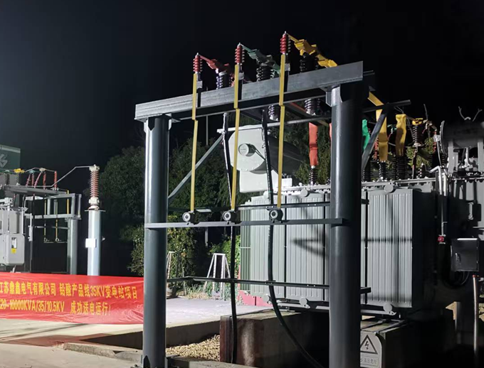
A transformer vector group identifies the winding connection arrangement and phase displacement between the high-voltage (HV) and low-voltage (LV) sides.
According to IEC 60076-1, transformer connection symbols indicate the winding configuration and the corresponding phase relationship.
| Symbol | Meaning | Engineering Function |
|---|---|---|
| D | HV winding connected in Delta (Δ) | Provides a closed path for certain circulating currents |
| y | LV winding connected in Star/Wye (Y) | Supports three-phase low-voltage distribution |
| n | Neutral terminal brought out on LV side | Enables three-phase, four-wire systems |
| 11 | Clock-hour designation | LV voltage leads HV voltage by 30° |
IEC transformer vector groups use a clock notation system to describe the phase displacement between the primary and secondary windings.
The HV reference phasor is positioned at 12 o'clock, while the corresponding LV phasor is positioned according to the vector group number.
For Dyn11, the LV phasor is positioned at 11 o'clock, representing a 30° lead relative to the HV reference.
This phase relationship is particularly important when evaluating transformer parallel operation, network expansion, and replacement equipment.
For example, Dyn11 and Dyn1 transformers have different phase displacements and cannot normally be connected directly in parallel on the same busbar.
Unbalanced phase loading is one of the most common operating conditions in low-voltage distribution networks.
Commercial buildings, residential complexes, shopping centers, and industrial facilities often contain a mixture of single-phase equipment, including lighting, air conditioning, computers, and electronic power supplies.
These loads rarely draw identical currents from all three phases.
Challenges with Yyn0 Transformers
In a Yyn0 transformer, both high-voltage and low-voltage windings use star connections with no phase displacement.
Where the winding neutrals and magnetic circuit do not provide an adequate zero-sequence current path, substantial unbalanced loading can cause neutral displacement and undesirable phase-to-neutral voltage variations.
The severity depends on the winding arrangement, grounding method, core construction, and system impedance.
Advantages of Dyn11 Transformers
The delta-connected HV winding provides a closed path for circulating currents associated with zero-sequence components.
This helps maintain more stable phase-to-neutral voltages under appropriate grounding conditions and reduces some of the limitations encountered with star-star arrangements lacking a stabilizing delta winding.
As a result, Dyn11 transformers are well suited to many distribution networks supplying significant single-phase loads.
However, the Dyn11 designation alone does not guarantee a universal 100% unbalanced-load capability. The permissible load imbalance depends on the winding design, thermal capacity, neutral terminal rating, and manufacturer's specifications.
Modern electrical networks increasingly contain nonlinear loads, such as:
Variable Frequency Drives (VFDs)
Switch-mode power supplies
Data center IT equipment
EV charging equipment
Solar photovoltaic inverters
Battery energy storage converters
These devices can generate harmonic currents that contribute to additional transformer losses, overheating, and power quality problems.
Triplen harmonics, including the third, ninth, and fifteenth orders, are particularly important in three-phase, four-wire distribution networks because their zero-sequence components can accumulate in the neutral conductor.
How the Delta Winding Helps
The delta-connected HV winding provides an internal circulation path for appropriate triplen harmonic components.
These circulating currents can reduce the transfer of zero-sequence harmonic currents to the upstream high-voltage line conductors.
This is one of the practical advantages of Dyn11 transformers in distribution systems containing nonlinear electrical loads.
However, a Dyn11 transformer does not eliminate all harmonic distortion.
Fifth-, seventh-, eleventh-, and other non-triplen harmonics may still propagate through the transformer. Internal circulating harmonic currents can also contribute to additional winding heating.
For installations with high nonlinear loading, engineers should evaluate total harmonic distortion (THD), harmonic current spectrum, additional winding losses, temperature rise, and neutral conductor sizing.
A Dyn11 connection is a useful design feature, but it does not replace a complete harmonic analysis or dedicated harmonic mitigation equipment where required.
Reliable ground-fault protection is essential for personnel safety and electrical equipment protection.
When a single-phase-to-ground fault occurs in a low-voltage network, the available fault current depends on the complete electrical fault loop.
This includes transformer impedance, neutral grounding, cable impedance, conductor characteristics, and the protection system.
In a Dyn11 transformer with an effectively grounded LV neutral, the delta HV winding can support internal zero-sequence current circulation.
This arrangement often provides favorable zero-sequence characteristics for low-voltage earth-fault analysis.
Why This Matters for Electrical Protection
An appropriate fault-current path helps protective devices detect and clear faults within the required disconnection time.
However, lower zero-sequence impedance does not automatically guarantee instantaneous circuit-breaker operation.
Electrical engineers must verify:
Minimum prospective earth-fault current
Maximum prospective short-circuit current
Circuit-breaker and fuse operating characteristics
Protection selectivity and coordination
System grounding arrangement
Transformer short-circuit withstand capability
Therefore, the transformer vector group must be coordinated with the complete electrical protection design.
Transformer magnetic performance is influenced by winding connections, core construction, operating voltage, and load conditions.
Under unbalanced excitation, zero-sequence flux may follow different magnetic paths compared with balanced three-phase operation.
In some star-star transformer arrangements, these effects can contribute to undesirable voltage behavior, additional losses, or localized heating.
The delta winding in a Dyn11 transformer provides a circulating current path that can counteract certain zero-sequence magnetizing effects.
This can improve transformer performance under specific unbalanced operating conditions.
However, magnetic saturation, audible noise, and insulation aging also depend on voltage magnitude, frequency, core materials, harmonics, and temperature.
For long-term reliability, transformer buyers should evaluate the complete electromagnetic and thermal design rather than relying solely on the vector group.
Understanding the differences between Dyn11 and Yyn0 helps engineers select the appropriate transformer configuration for their distribution systems.
| Technical Parameter | Dyn11 Transformer | Yyn0 Transformer |
|---|---|---|
| HV Winding Connection | Delta (Δ) | Star (Y) |
| LV Winding Connection | Star with Neutral | Star with Neutral |
| Phase Displacement | LV leads HV by 30° | 0° |
| Three-Phase Four-Wire Supply | Supported | Supported |
| Unbalanced Load Performance | Generally favorable due to delta circulation path | More dependent on grounding and core design |
| Triplen Harmonic Behavior | Provides internal circulation path | No inherent delta circulation path |
| Zero-Sequence Characteristics | Often favorable for grounded LV networks | Depends strongly on grounding and construction |
| Ground-Fault Protection | Supports appropriate fault-current paths | Requires system-specific assessment |
| Parallel Operation | Compatible with appropriately matched vector groups | Cannot directly parallel with Dyn11 |
| Typical Applications | Commercial, Industrial, Utility Distribution | Selected Distribution and Auxiliary Applications |
Not necessarily.
Dyn11 is a strong option for many medium-voltage to low-voltage distribution systems, especially where significant single-phase loading and a grounded LV neutral are required.
However, Yyn0 may remain suitable for applications with relatively balanced loading or systems specifically designed around star-star connections.
Other configurations, including Yzn11, Dyn1, and YNd11, may also be specified depending on network voltage levels, grounding arrangements, and local utility requirements.
The most suitable vector group is the one that matches the electrical system design rather than simply the configuration used most frequently.
EV charging infrastructure requires reliable power distribution, adequate transformer capacity, and coordinated electrical protection.
High-power DC charging systems use electronic converters that may introduce harmonic currents into the electrical network.
Dyn11 transformers can provide a practical configuration for the grounded low-voltage distribution network supplying EV charging equipment.
However, harmonic performance must be evaluated according to the charger converter topology and actual operating conditions.
Solar photovoltaic installations and battery energy storage systems introduce additional considerations for transformer selection.
These include bidirectional power flow, variable operating conditions, grounding requirements, and inverter-generated harmonics.
Dyn11 transformers may be suitable for auxiliary distribution systems and selected step-down applications in renewable energy projects.
For inverter step-up transformers, the appropriate vector group must be selected according to the inverter design, grounding philosophy, protection scheme, and grid interconnection requirements.
Data centers and commercial facilities operate a combination of three-phase and single-phase electrical loads.
These may include UPS systems, server equipment, lighting, HVAC systems, and facility management equipment.
Dyn11 transformers can support three-phase, four-wire distribution networks with an accessible low-voltage neutral.
For data center applications, engineers must also evaluate neutral currents, harmonic loading, redundancy, short-circuit protection, and overall electrical reliability.
Industrial facilities often contain motor drives, automated machinery, electronic control systems, and single-phase auxiliary loads.
Dyn11 transformers can provide favorable operating characteristics for many industrial low-voltage distribution networks.
Their winding configuration is particularly useful where grounded neutral systems and mixed three-phase and single-phase loads are required.
Transformer selection should also consider motor starting conditions, harmonic distortion, load fluctuations, and protection coordination.
Choosing a Dyn11 transformer involves more than specifying the vector group.
EPC contractors, utility engineers, and procurement managers should evaluate the following technical parameters before purchasing equipment.
The transformer voltage ratings must match the medium-voltage supply network and the required low-voltage distribution system.
Common project configurations may include:
| Transformer Voltage | Typical Application |
|---|---|
| 10/0.4 kV Dyn11 | Industrial and Municipal Distribution |
| 11/0.415 kV Dyn11 | Commercial and Utility Distribution |
| 20/0.4 kV Dyn11 | Regional MV/LV Distribution |
| 33/0.415 kV Dyn11 | Selected Industrial and Infrastructure Projects |
These configurations are illustrative examples. Actual ratings depend on local utility requirements and project specifications.
Transformer capacity should be determined according to maximum apparent power demand, expected load growth, ambient conditions, harmonic loading, and operational requirements.
Transformer percentage impedance directly affects prospective short-circuit current and voltage regulation.
An excessively low impedance may result in high fault-current duties, while excessive impedance can cause undesirable voltage drops during operation.
The specified impedance should be coordinated with downstream switchgear, cables, protective devices, and the overall electrical distribution design.
For installations containing large numbers of VFDs, rectifiers, UPS systems, and other nonlinear loads, transformer thermal performance requires additional consideration.
Harmonic currents may increase winding losses and stray losses, potentially affecting temperature rise and insulation life.
Engineering specifications should therefore identify significant harmonic loading conditions and any additional thermal design requirements.
An accessible neutral terminal does not automatically determine the electrical grounding arrangement.
The system designer must establish the applicable earthing configuration and verify the corresponding protection requirements.
For low-voltage networks, grounding arrangements such as TN, TT, and IT systems require different protection considerations.
When replacing an existing transformer or expanding a distribution network, electrical engineers must verify:
Vector group and phase displacement
Phase sequence
Voltage ratio
Tap positions
Short-circuit impedance
Load-sharing characteristics
Protection compatibility
Two transformers with identical rated capacities may still be unsuitable for direct parallel operation.
Yes. Dyn11 transformers can operate in parallel when the necessary electrical compatibility conditions are satisfied.
The main requirements include matching phase displacement, phase sequence, compatible voltage ratios, and suitable short-circuit impedance characteristics.
For example, Dyn11 and Dyn1 transformers have a 60° phase-displacement difference.
Connecting these transformers directly in parallel on the same busbar can produce severe circulating currents and damage electrical equipment.
Therefore, transformer nameplate information, technical specifications, and relevant test records should be reviewed before connecting additional transformers to an existing distribution network.
IEC 60076-1 provides the foundational requirements for power transformers, including connection symbols, technical ratings, and general specifications.
Other relevant IEC standards address temperature rise, insulation performance, short-circuit withstand capability, and dry-type transformer construction.
| IEC Standard | Main Technical Scope |
|---|---|
| IEC 60076-1 | Power Transformers – General Requirements |
| IEC 60076-2 | Temperature Rise for Liquid-Immersed Transformers |
| IEC 60076-3 | Insulation Levels and Dielectric Tests |
| IEC 60076-5 | Ability to Withstand Short Circuit |
| IEC 60076-11 | Dry-Type Power Transformers |
Compliance should be verified against the applicable transformer design documentation and test reports.
For international projects, additional regional standards, utility specifications, and grid codes may also apply.
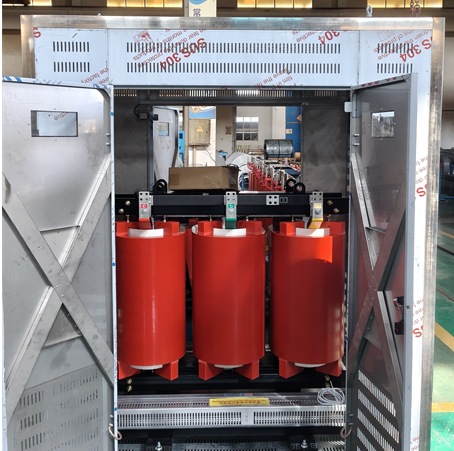
Selecting a reliable transformer manufacturer involves more than comparing equipment prices.
Manufacturing capability, engineering expertise, product testing, specification flexibility, and project support are important factors in long-term transformer performance.
Jiangsu Dingxin Electric is a power transformer manufacturer with more than 30 years of industry experience, providing electrical transformer solutions for utility, industrial, commercial, and infrastructure applications.
Dingxin Electric manufactures a range of transformer and power distribution equipment, including:
For projects requiring Dyn11 or other specified vector groups, customers can submit their technical requirements for engineering evaluation and customized transformer solutions.
| Specification | Required Information |
|---|---|
| Transformer Type | Oil-Immersed or Dry-Type |
| Rated Capacity | kVA or MVA |
| HV/LV Voltage | Primary and Secondary Rated Voltage |
| Vector Group | Dyn11 or Project-Specific Requirement |
| Rated Frequency | 50 Hz or 60 Hz |
| Short-Circuit Impedance | Percentage or Project Requirement |
| Cooling Method | Application-Specific Cooling Arrangement |
| Tap Range | Required Voltage Adjustment |
| Installation | Indoor, Outdoor, Pad-Mounted, or Substation |
| Applicable Standards | IEC, IEEE, ANSI, or Local Utility Requirements |
| Special Conditions | Harmonics, Load Unbalance, Ambient Temperature, or Other Requirements |
Providing complete electrical specifications allows the manufacturer to review technical requirements, identify possible design considerations, and prepare a suitable quotation.
Dyn11 is a transformer vector group in which the high-voltage winding is connected in delta and the low-voltage winding is connected in star with an accessible neutral. The number 11 indicates that the low-voltage phasor leads the high-voltage reference by 30° under IEC clock notation.
Dyn11 is widely used because the low-voltage star winding provides a neutral terminal for three-phase, four-wire distribution systems, while the high-voltage delta winding provides useful circulation paths for zero-sequence and certain triplen harmonic currents.
Dyn11 uses a delta-connected HV winding and a star-connected LV winding with a 30° phase displacement. Yyn0 uses star connections on both sides with zero phase displacement. Their zero-sequence behavior, grounding characteristics, and performance under unbalanced loads can also differ.
Dyn11 and Dyn1 have similar delta-star winding arrangements but different phase displacements. Dyn11 has a 30° LV lead, while Dyn1 has a 30° LV lag. The appropriate configuration depends on existing network equipment, utility standards, and electrical system requirements.
Dyn11 transformers can provide favorable performance under unbalanced loading, but a universal 100% load-unbalance rating should not be assumed. The permissible imbalance depends on transformer winding design, neutral current rating, thermal capability, and manufacturer specifications.
The delta winding provides an internal circulation path for appropriate triplen harmonic components, reducing their transmission as zero-sequence currents into the upstream HV lines. However, Dyn11 does not eliminate all harmonics, and circulating currents can still contribute to transformer heating.
Dyn11 and Yyn0 transformers cannot normally be connected directly in parallel on the same busbar because they have different phase displacements. Direct parallel connection can create damaging circulating currents unless a properly engineered phase-shifting arrangement is used.
Yes. Dyn11 may be suitable for certain distribution and auxiliary power applications in solar PV and battery energy storage projects. However, the transformer vector group for inverter interfaces must be selected according to grounding requirements, inverter design, protection coordination, and utility interconnection specifications.
Dyn11 is a practical option for many data center distribution networks requiring a grounded low-voltage neutral and a combination of three-phase and single-phase loads. Engineers must also consider UPS harmonics, neutral current, redundancy, thermal performance, and electrical protection.
Dyn11 is a vector group designation based on IEC transformer connection and clock notation. IEEE standards also address delta-wye transformer connections, but the precise winding arrangement and phase displacement must be verified. Not every delta-wye transformer is automatically equivalent to IEC Dyn11.
There is no universal zero-sequence impedance value for all Dyn11 transformers. It depends on winding construction, core design, leakage flux paths, and grounding arrangements. Engineers should obtain the relevant transformer impedance data from the manufacturer for protection and fault calculations.
Yes. Dyn11 describes the transformer winding connections and phase displacement rather than its insulation or cooling technology. It can be specified for appropriately designed oil-immersed and dry-type distribution transformers.
Dyn11 transformers are available in various voltage configurations depending on the distribution network. Common examples include 10/0.4 kV, 11/0.415 kV, and 20/0.4 kV. Higher primary voltage configurations may also be available depending on engineering and utility requirements.
When selecting a manufacturer, evaluate its engineering experience, applicable manufacturing standards, technical documentation, testing capability, customization options, and after-sales support. The manufacturer should be able to review your rated voltage, capacity, impedance, grounding, and application requirements before finalizing the transformer specification.
Dyn11 has become a widely preferred transformer vector group in many modern medium-voltage and low-voltage distribution networks.
Its combination of a delta-connected high-voltage winding and a star-connected low-voltage winding with an accessible neutral offers practical advantages for three-phase, four-wire systems.
These advantages include favorable performance under certain unbalanced loading conditions, useful triplen harmonic containment, and zero-sequence characteristics that can support appropriately designed ground-fault protection systems.
However, Dyn11 should not be considered universally superior to every other transformer vector group.
The final selection must account for electrical system design, transformer capacity, harmonic loading, grounding requirements, phase displacement, protection coordination, and local utility specifications.
For EPC contractors, electrical consultants, utility engineers, and industrial procurement teams, choosing the appropriate vector group is an important step toward building reliable and efficient power distribution infrastructure.
Looking for an oil-immersed distribution transformer, dry-type transformer, or customized Dyn11 transformer for your next power distribution project?
With more than 30 years of transformer manufacturing experience, Jiangsu Dingxin Electric provides electrical transformer solutions for industrial, utility, and infrastructure applications.
Our team can review your project specifications, including transformer capacity, voltage ratings, vector group, short-circuit impedance, installation conditions, and applicable technical standards.
Contact Dingxin Electric today to request transformer technical specifications, engineering consultation, or a customized quotation.
Website: https://global.dingxinelectric.com/

Jiangsu Dingxin Electric, a high-tech power equipment manufacturer, produces high-quality transformers and substations, serving global markets across 30+ countries.
Room 118, Building 8, 2999 Hutai Road, Baoshan District, Shanghai, China


Copyright © Jiangsu Dingxin Electric Co., Ltd. All Rights Reserved | Privacy Policy
 EN
